OLED Controller
This project is all about giving a little bit of personality to an OLED driver. No particular reason - just pure experimentation. The firmware is a simple controller that receives image data and sends it to the OLED screen. The desktop application is written in Python using PySide6 and provides a gallery of images and animations to send to the device.
Hardware
OLED Screen
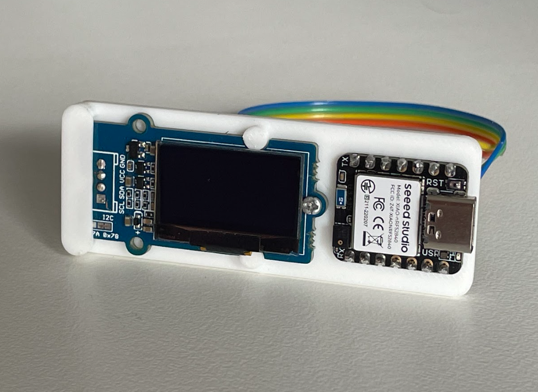
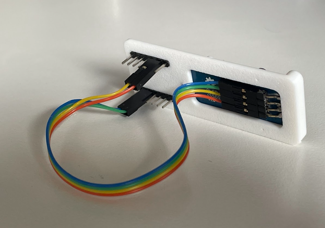
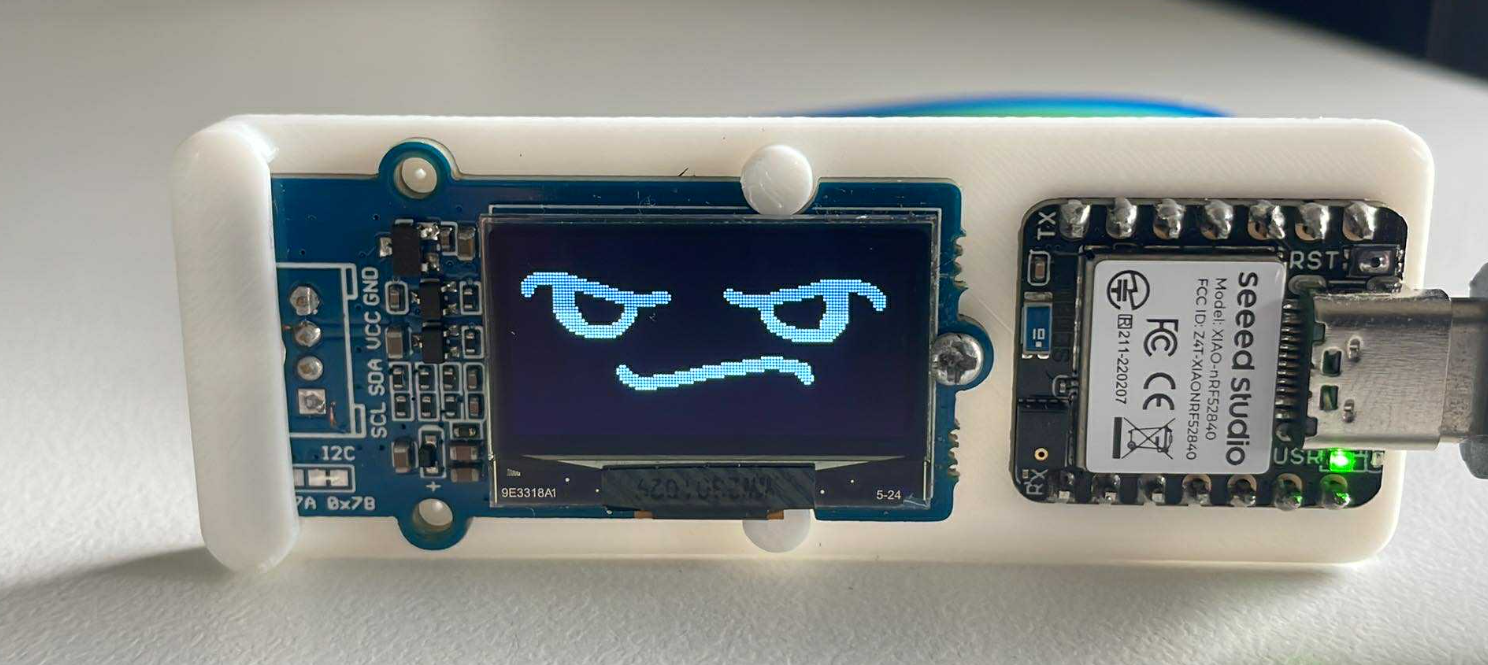
The Grove - OLED Display 0.96” (SSD1315) is a monochrome 128x64 pixel display. I removed the 4-pin I2C header and moved it to the back because I didn’t want the wires sticking out over the screen.
Controller
A Seeed Studio XIAO nRF52840 Sense was perfect for this project. It’s tiny, has a nice USB interface, and it has several GPIOs to utilize. This board has lots of features that I don’t need (BLE, IMU, microphone, battery charging, additional flash, etc.). Maybe in the future I will utilize some of these features, e.g. I could add a battery and use BLE to send images instead of serial USB.
Casing
The casing is 3D printed and only really serves to hide the wires and provide a bit of rigidity. The XIAO nRF52840 Sense is press-fitted so it can be easily removed and repurposed if needed for other projects. The OLED display is held in with a single screw so can also be removed and repurposed.
Firmware
Most of the functionality was provided by the olikraus/U8g2 library. The XIAO nRF52840 Sense is designed for use with Arduino. I am not a fan of the Arduino IDE so I decided to try using PlatformIO, which I had not used before, and was pleasantly surprised to find it was very easy to set up.
Driver
The driver is simple, most of the actual logic is handled by the library. All I needed to do was initialize a driver instance and draw a bitmap.
1
2
3
4
5
6
7
8
9
10
#include <U8g2lib.h>

static U8G2_SSD1306_128X64_NONAME_F_HW_I2C u8g2(U8G2_R0, /* clock */ SCL, /* data */ SDA, /* reset */ U8X8_PIN_NONE);

void oled_init()
{
    u8g2.begin();
    u8g2.clearBuffer();
    u8g2.setFont(u8g2_font_ncenB12_tr);
}
1
2
3
4
5
6
7
8
9
10
oled_set_image_ret_t oled_set_image(const uint8_t *image_data, size_t length)
{
    if (length != OLED_BUFFER_SIZE)
    {
        return OLED_SET_IMAGE_INVALID_LENGTH;
    }
    u8g2.drawXBMP(0, 0, OLED_WIDTH, OLED_HEIGHT, image_data);
    u8g2.sendBuffer();
    return OLED_SET_IMAGE_SUCCESS;
}
Protocol
I created a simple [header][length][payload][crc] protocol with the following state machine:
flowchart TD
    HEADER_LSB -->|byte == 0xAA| HEADER_MSB
    HEADER_MSB -->|byte != 0x55| HEADER_LSB
    HEADER_MSB -->|byte == 0x55| LENGTH_LSB
    LENGTH_LSB -->|any byte| LENGTH_MSB
    LENGTH_MSB -->|length > 1024| HEADER_LSB
    LENGTH_MSB -->|length <= 1024| DATA
    DATA -->|received all bytes| CRC_LSB
    CRC_LSB -->|any byte| CRC_MSB
    CRC_MSB -->|crc match
    \ send ack
    \set image| HEADER_LSB
    CRC_MSB -->|crc mismatch
    \ send nack| HEADER_LSB
When a full packet is received, it’s sent to the OLED driver. 1024 bytes are required because each pixel on the OLED display is a bit. There are 128x64 pixels, which is 8192 pixels, which is 1024 bytes.
LEDs
I wanted some feedback to know what the feedback was doing, so added some LED states:
- Green when the board is powered and functional
- Blue when the device is receiving a packet
- Red when the OLED image is being set
- White when there is an error (packet CRC doesn’t match, or failed to set the image)
Desktop Application
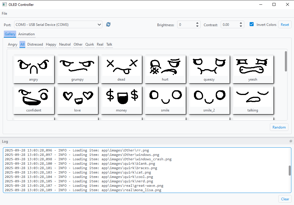
Simple choose the correct serial port, browse the gallery of 128x64 images, and send to the device.
Dithering
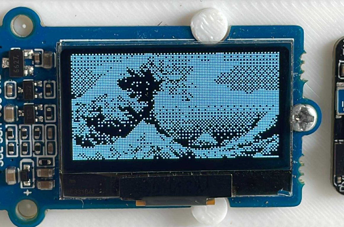
For images that aren’t plain black and white, it’s possible to convert to grayscale and use a middle-level threshold to determine if a pixel should be displayed as a black pixel or a white pixel. This doesn’t look great for some images, so I added dithering for non-binary images.
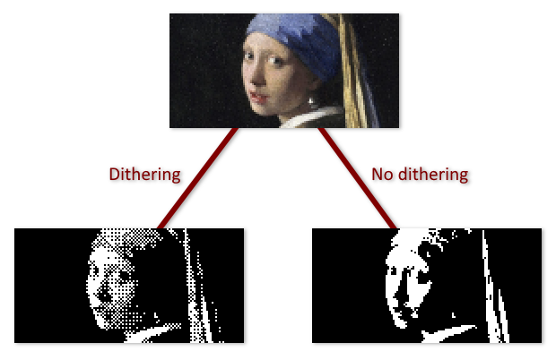
I used the ordered dithering algorithm and a 4x4 Bayer matrix.
1
2
3
4
5
6
7
8
9
10
11
12
13
14
15
16
def dither_pixel(pixel: int, x: int, y: int) -> int:
    # 4x4 Bayer matrix (values scaled 0-15)
    bayer4 = [
        [0, 8, 2, 10],
        [12, 4, 14, 6],
        [3, 11, 1, 9],
        [15, 7, 13, 5],
    ]

    # choose matrix cell
    threshold_map_value = bayer4[y % 4][x % 4]

    # scale Bayer value (0-15) to 0-255
    bayer_threshold = (threshold_map_value + 0.5) * (255 / 16)

    return 1 if pixel < bayer_threshold else 0
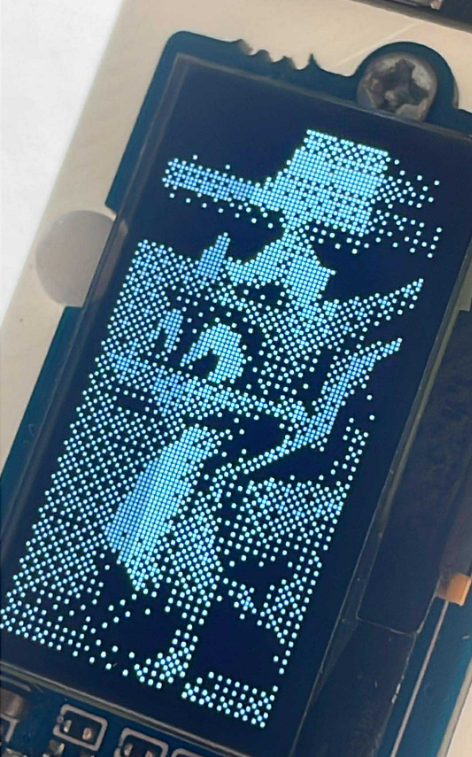
Dithering proves to be quite effective in creating the illusion of gray pixels:
Animations
Animations are also possible by defining frames and intervals. The app sets up a timer and sends the frames.